We’ll pour the metals that other investment foundries won’t or can’t ....
Positive Metal Identification
Whether a part has a complex or simple configuration ....
With investment castings you put metal where you need it ....
Competitive pricing is a key component at Nova Precision.
Providing you with consistency and the foremost metallurgical know how ....
Service is provided by all the key players ....
Using our Import experience, these cast parts can be shipped directly to you ....
Recycling is key....
Phone, Fax, Email

The term foundry engineering is a loose industry term applied to an area of technical parameters related with producing a solid and dimensionally correct part.  The parameters include the “feeding” reservoirs or heads and risers for providing liquid metal during solidification;  the design and dimensioning of the “plumbing system” or gating for accepting the metal and introducing it into the mold cavity;  the “contacts”  for connecting the mold cavity to the gating and risers.  The above parameters must also include consideration of whether the part will be subject to distortion while cooling to room temperature.  All of this gets rolled into the starting design of the tooling and the establishment of the original dimensions of the tool to allow for wax dimensional changes and casting cooling dimensional changes.  The above considerations also dictate what is possible when specific molding material and investing techniques are applied. 

Risers.  A physical reality is that commercially cast metals all undergo a volumetric change upon solidification.  The primary function of a riser is to provide the liquid metal to a solidifying section of a casting thus containing all of the shrinkage volume.  The riser is subsequently sectioned from the casting giving a solid casting.  The design of a riser depends to a great deal on the on the type of metal being cast. Gray cast iron needs very little feeding since a period of graphitization occurs during the final stages of solidification that causes an expansion that tends to counteract metal shrinkage.  Steel or white cast iron, and many of the nonferrous alloys, which are commercially cast, have an extended solidification range and require extensive feeding systems.          

Material Volumetric shrinkage, %
Carbon Steel                2.5 – 3.0
1 % carbon steel 4.0
Pure aluminum  6.60
Pure copper   4.92
Gray cast iron 1.90 to negative depending on graphitization
White cast iron 4.0 – 5.50

Figure 1. 

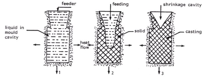
From a theoretical consideration the solidification of an alloy takes place as the result of heat loss from the casting, gating and risering surfaces. The design of the geometries and size of the risers must be so that they stay molten longer than the casting and can provide sufficient liquid metal to compensate for the volumetric shrinkage of the alloy. The contacts must also stay open, not solidify shut, to allow the flow of liquid metal through them to the casting. Figure 1. shows the simplest case possible for the design of a riser on a casting. With the use of freezing ratios of surface area of casting to volume of casting divided by surface area of riser to volume of riser considerations, a start can be made to correlate with volume ratios for specific metals and have a calculation base for determining riser sizes and shapes. However, the casting world is not blocks! Each section of a casting must be mathematically analyzed with the potential of one part of a casting feeding another section and the issue of non-cooling surfaces where adjoining sections meet, etc. 

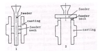
Riser size.  The diameter of a top riser must be larger than that of the casting since it would otherwise solidify before the casting, no matter how long it might be made.  The height of the riser should be about 1.5 times the diameter.  Additional height is no advantage since it means also additional surface area, and the extra metal is then merely feeding the lower part of the riser.  Investment casters often construct the riser as part of the gating for accepting the metal during pouring and providing the vertical plumbing for entry into multiple mold cavities.  This can be a very successful technique but is dependent on the type of metal being poured. 

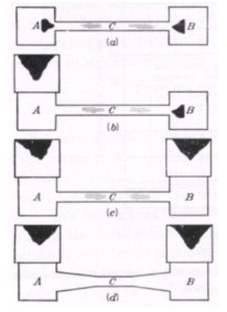
Positioning of risers.  A riser will not function properly unless it is located in a position that will result in directional solidification toward it from the casting.  The number of risers that must be assigned to a specific casting will depend upon how many of these directional paths must be operating to secure soundness.  Figure 2. shows a hypothetical casting having two heavy sections connected by a light section.  Only by risering both sections with a riser greater in diameter than the heavy section and properly padding the casting to promote directional solidification (d) is a sound casting obtained.  Figure 3. shows a correct design in example (1) of promoting directional cooling by correct gating design into thick sections and incorrect design in (2) with loss of optimum feeding temperature gradient during mold feeding.


Figure 2.                                                                Figure 3. 

Factors affecting riser efficiency.  An open riser must be as large as indicated because it is freezing while the casting is freezing hence only that portion of the metal in the riser which remains liquid longer than the casting is available for feeding.  If some means were available to utilize more of the riser metal to feed the casting, better riser efficiency would be obtained.  The following sections present some of the means presently employed for this purpose. 

Blind risers.  The conventional riser is open to the atmosphere.  The so-called blind riser is enclosed by the mold and is usually designed for a minimum surface area per unit volume.  Blind risers are only effective with alloys which form an outer skin during solidification such as with steels.  The design concept is that the outside metal areas of the mold solidifies early and the casting plus blind riser thereby constitute a closed shell of metal. This shell develops a partial vacuum by virtue of the shrinkage which occurs during solidification.  As the shrinkage occurs in the casting, metal is drawn in from the riser to compensate for it.  This can occur even though the riser is no higher than the casting, but the temperature gradient must be such that the casting freezes first.  If, in addition, the skin of the casting is strong enough and the skin of the blind riser is pierced to allow atmospheric pressure to exert an influence, the riser feeding is greatly enhanced by atmospheric pressur

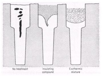
Antipiping and Exothermic Compounds.  A riser can be made more efficient by employing some artificial means to keep the top of the riser from freezing over so that the molten metal beneath can be exposed to atmospheric pressure.  This is a common practice and can be done by use of certain additions made to the surface of the molten metal in the riser soon after the metal enters the riser.  These additions serve as antipiping compounds through an insulating effect or from heat given off by an exothermic reaction in the compound.

 Figure 4.

Insulation of risers.  Besides supplying insulation on the top of the riser, it is also possible to use insulating sleeves or wraps on the sides of a riser.  This can enhance a lower solidification rate in the riser and hence better feeding of the casting.
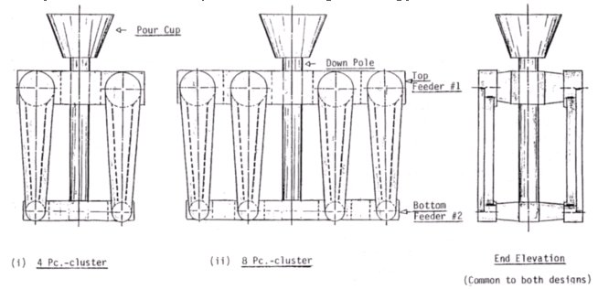
Insulating pads.  Insulation of selected parts of a mold can also decrease the cooling rate and promote directional solidification.  At times, foundry engineers will request an increase to a part section thickness to achieve this effect.

Chills.  The preceding discussions of risers deals with methods for securing directional solidification by selectively slowing the solidification process.  It is possible that the same objective of directional solidification can be accomplished by the reverse procedure of chilling the metal in those portions of the casting that are more remote from the liquid metal source.  Both external and internal chills can be used for this purpose.  External chills are placed in the mold walls at or close to the mold-metal interface while internal chills are placed in the mold cavity.  The practice of using chills is very common with sand molding techniques but is very selectively used by investment casters.  Investment casters must surmount the problem of surface oxidation or contamination of a chill when the shell is fired.  Although not strictly in the category of an external chill, the same effects can be accomplished by a variety of shell stucco materials selectively placed to change the cooling characteristics of the mold.  These can be viewed as extreme applications as they are very personnel and procedure sensitive techniques.

Feeding Distance.  A great deal of the discussion before this has centered on producing a completely sound casting with no shrinkage cavities contained in the part.  This is an objective, which is seldom achieved in practice.  The normal situation is to recognize that shrinkage cavities will occur and that a job of the foundry engineer is to have them in a location, which is not detrimental to the end use of the part.  As an example, as parts are normally designed, they have uniform wall thickness.  Liquid metal moving in these walls during solidification is quickly restrained by freezing metal from the walls.  The general rule is that a uniform wall will only be sound for a length of twice the section thickness from the feeding section.  After that length there will be uniformly dispersed shrinkage in the thermal center of the section.  Overwhelmingly, in most situations this is not a problem.  If it is, then the foundry engineer, in conjunction with the design engineer, will consult on how to address the problem.  For real world castings, thermal cooling gives very complex solidification problems.  As a further example, when a part has a hole in a section, the size of the hole becomes significant relative to the outside diameter and length of the part.  If the hole is less than approximately one-third of the outside diameter, there is usually insufficient cooling to the center hole to consider this surface as a cooling surface.  It is said that “the casting does not know it has a hole in it” from a solidification perspective.  If the hole is greater than approximately two-thirds of the outside diameter, there is usually sufficient cooling to the center hole to consider the ring as a uniform section part.  Between these two rough dimensions, many other factors start to become significant such as what is at the end of the holes (blind hole vs. open hole), length of hole, etc.

Gating.  The design of a correct gating system is another foundry engineering task, which is dependent on the metal being cast.  The objective is to introduce the metal from the ladle or furnace in a non-turbulent manner during the entire filling of the mold cavity.  Reaction of the metal with atmospheric oxygen can lead to both micro and macro inclusions in the part.  Parts are normally cast with minimal superheat above their solidification temperature.  If the pouring rate is too slow, the metal will solidify before completely filling the mold cavity.  But, there are limits to higher pouring temperatures to compensate because of increased liquid shrinkage of excess temperatures and metallurgical problems associated with dissolved gases. The general rule is that for each increase of 212F the volume of liquid metal shrinkage increases by 1%.

Contacts.  The issue of contacts, the connections between the part cavity and the gating and risers, was discussed from the feeding perspective earlier.  Another significance of contact design is the removal of the desired part from the attached gating system and the subsequent grinding of the contact surface.  The objective is to minimize their size from a finishing of the casting perspective.  Their location and number can also be significant from the dimensional tolerance perspective of the finished part and the structural stability of the wax tree during the investing process.

Figure 5.

Figure 5. shows two possible assemblies of a crank arm casting with 4 per tree and 8 per tree.  The design feeds the heavy sections of the casting, introduces metal to the mold cavity from a bottom up filling, has tapered contacts which can be cut with an abrasive cut-off wheel and leaves a reference surface around the contacts for visually grinding the contacts flat.

Dimensional tolerance.  The foundry engineer is again expected to produce a cast part to the desired finished dimensions.  Expansion and contraction of the injected waxes starts the complication of determining finished dimensions.  Warm waxes will contract approximately 1% from the tool dimension when cooled to room temperature.  They are subject to distortion by physical restraint and cooling gradients in the tool and handling after removal from the tool.  These potential problems must be identified and adjusted for along with physical restraints and differential cooling gradients of the part from the solidification temperature.  The mold cavity needs to be approximately 2% larger than the finished desired dimension for most steels.  This approximation will vary substantially with the type of metal being cast.  With the large number of possibilities which will affect the finished dimension, a tolerance must be applied to the finished part.  The general rule of thumb for dimensional tolerances is plus/minus .010 inch for the first inch of dimension plus and additional plus/minus .005 inch for each additional inch of dimension.  This is a rough estimate and can be applied without other specific information on a part.  It also applies to all dimensional tolerances such as length, flatness, roundness, etc.

Summary.  This discussion is not an all encompassing presentation of the issues involved.  The casting industry relies on experience of foundry engineers to produce a competitive product.  Many years of experience are embodied when a sketch of the gating and risering system is made.  The principles are based in science, principally heat transfer and fluid mechanics, but are not ready to be reduced to a simple plug in the parameters computer program.  Three dimensional modeling to just describe the shape of a part still requires superior computer systems to perform the calculations in real time.  Add to this the matrix of possibilities to approach the problem and the heading and gating of a single part soon becomes a research program to produce reliable information.

e forcing liquid metal into the shrinkage areas as they develop.  The skin of the riser can be kept open by using design techniques such as insertion of small diameter stock cores or sharp corner “hot spots”.  When a blind riser is used in this manner it is referred to as an atmospheric or pressure riser.  There is no advantage in providing atmospheric pressure feeding for metals which do not readily form a solid skin during solidification because the partial vacuum necessary for the success of this method is not created.